Project 1 - Robotic arm for use in automated inspection systems.
Why?
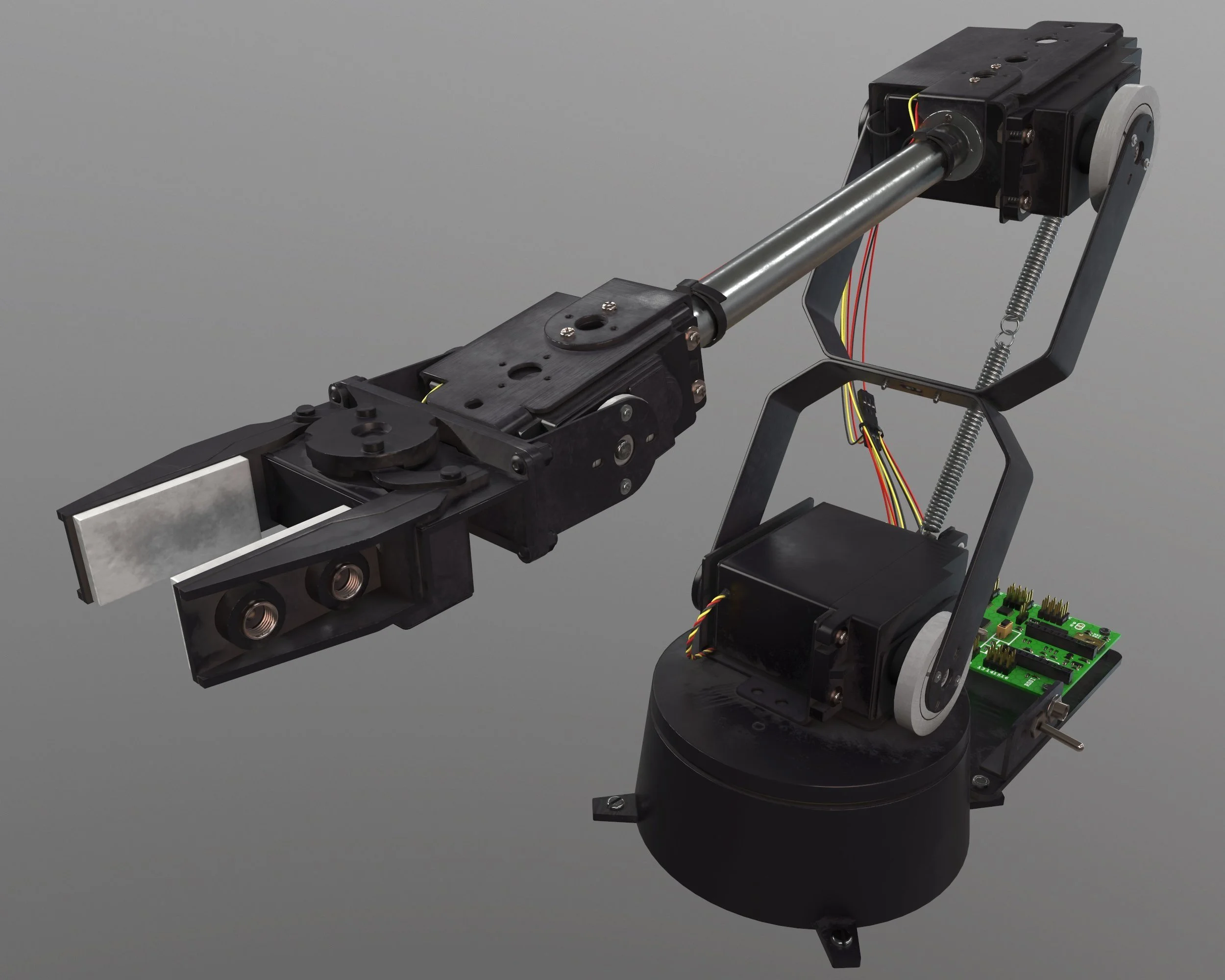
For this project we were given a brief to modify a robotic arm and create a viable prototype for an application of our choosing.
The robotic arm was developed to enhance precision and efficiency in automated inspection systems during a university group project. It aimed to reduce human error, increase inspection speed, and enable consistent quality control in manufacturing processes. The design focused on adaptability and ease of integration with existing systems, addressing practical challenges faced in automated visual and tactile inspections.


How?
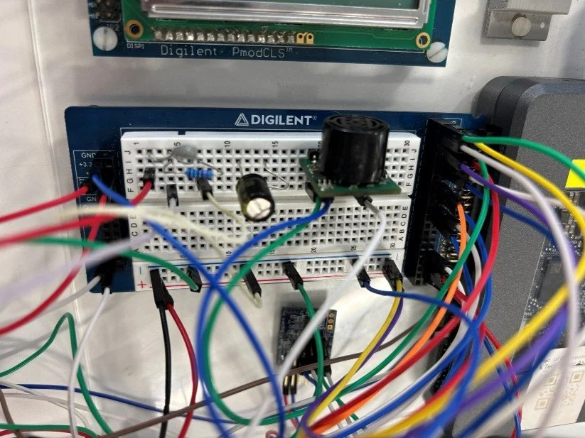
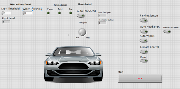
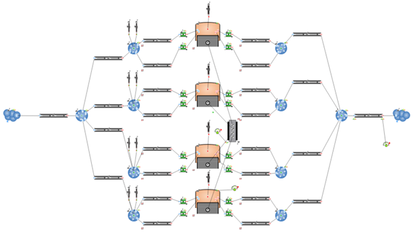
Using a commercially available robot arm, modifications were made to extend the reach, improve the practicality through custom grippers, and a fully custom control program was developed to ease user function and control movement. During the project I assisted with the creation of designs (using SolidWorks) for custom grippers to aid in retention during motion. I also worked as the solo software engineer in order to create an easily usable UI and a functioning program to communicate with the control board. The control program included inverse kinematics calculations to ensure the end effector stayed parallel during automated operation and a teaching mode to allow the operator to set a tool path. The program should run fully unassisted after teaching, moving a bolt from a rack and place it within an inspection area, then taking input (simulated from the user) as to whether the part be rejected or approved and place appropriately.
Results
All specified brief requirements were successfully met. A fully functional and repeatable system was developed, demonstrating consistent and repeatable performance across multiple iterations. Throughout the development process, strict adherence to established robotics standards was maintained, ensuring compliance with industry best practices and safety regulations. The final system satisfied all mandatory and operational criteria.
Project 2 - Conceptual Design of a Formula Student Chassis.

Why?
This project brief was based on the UWE Formula Student Team, to design a chassis capable of being used in FSUK competitions.
The chassis design was driven by the strict technical and safety regulations set out by Formula Student UK (FSUK). These rules, detailed in section T3 of the FS rulebook, mandate structural components such as front and main roll hoops, impact attenuators, bulkheads, and side-impact protection. Material requirements and tube dimensions are clearly defined to ensure safety in dynamic events. Meeting these regulations was essential not only for competition eligibility but also to ensure the structural integrity and driver protection throughout all race conditions.

How?
The chassis was designed by selecting a steel spaceframe structure that conforms to Formula Student UK (FSUK) regulations. Key steps included choosing an optimal powertrain (a Triumph Street Triple engine), selecting materials (AISI 4130 steel tubes of varying thickness), and constructing the frame to meet stiffness, weight, and safety requirements. Chassis iterations were designed using SOLIDWORKs, and analysed using FEA simulations, and improvements were made to enhance torsional stiffness and integrate suspension components effectively.

Results
The final chassis achieved a torsional stiffness of about 2520 Nm/deg with a mass of 32.71 kg, meeting all FSUK and UWE regulations/requirements. FEA tests confirmed the design’s compliance and robustness under impact and torsional loads. The final design improved the stiffness-to-mass ratio slightly and provided better mounting options for the suspension, positioning it as a strong foundation for future development compared to the current chassis in use.
Project 3 - Simulation and analysis of Electric Vehicle Drivetrains solutions.
Why?
This project was my final year engineering project, based on my experience in the automotive trade as well as my studies.
The research aimed to address range anxiety, a major barrier to EV adoption, by investigating how drivetrain configuration influences efficiency and thus driving range. Since drivetrain losses contribute significantly to power consumption, understanding and optimising drivetrain layouts can help improve EV performance, battery health, and user confidence — supporting global emissions targets and consumer adoption.

How?
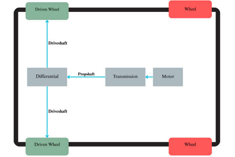
The study simulated and analysed the efficiency of various electric vehicle (EV) drivetrain configurations using a mid-sized EV model (based on the BMW i4) in MATLAB/Simulink. Different drivetrain types — such as single motor single axle , dual motor , axle-mounted , and hub-driven systems — were modelled. Vehicle and motor parameters were standardised, and a custom UK drive cycle (urban + motorway) was used.
Each system used a custom designed motor profile, using ANSYS Electronics desktop to model and validate the motor designs.
Powertrain losses, battery state of charge (SoC), and current profiles were evaluated to compare efficiency.

Results
The hub-driven all-wheel-drive (HD AWD) configuration showed the highest efficiency, maintaining better SoC and stable battery current, thanks to motors staying closer to their optimal efficiency range. Conversely, the SMSA configuration was least efficient due to its single large motor operating outside its peak range during high-load conditions. The HD AWD and axle-mounted systems offered a good balance of efficiency and performance across varying drive scenarios, suggesting that alternative drivetrain layouts could improve EV range and viability.
Project 4 - Android Application to track real-time vehicle movement for use in discrete simulation.

Why?
This was a sub-project for the previous research in EV efficiency.
The custom Android app was created because standardised drive cycles (like FTP75, CADC) do not accurately represent modern UK driving conditions or longer journeys. A realistic, location-specific drive cycle was essential for producing meaningful and applicable results when simulating EV efficiency under typical UK urban and motorway conditions.

How?
An Android application was developed using Android Studio to record real-world driving data for simulation purposes. The app collected GPS data at a 1-second interval, capturing speed, elevation, time, and location over a 182 km journey between Bristol and Southeast London. After recording, the app exported the data to a text file, which was processed in MATLAB. Elevation data was refined using a Python script that queried Google’s Elevation API to improve accuracy, and the resulting dataset was smoothed with a moving-mean filter to reduce noise.

Results
The app successfully captured a detailed drive cycle comprising both city and motorway segments, totalling 182 km over ~2.5 hours with realistic stop-and-go and high-speed phases. This dataset enabled high-fidelity simulation of EV drivetrain performance, providing a better basis for comparing configurations under realistic, representative driving scenarios.